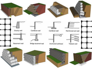
Geosynthetics is a general term for various products made of synthetic materials used in geotechnical and civil engineering construction. Synthetics are high molecular polymers, which are made from chemicals extracted from coal, oil, natural gas or limestone, and are further processed into fibers or synthetic sheets, and finally made into various products. Geosynthetics have many mechanical properties. When testing their material properties and product quality, the test items mainly include tensile strength, bursting strength, tear strength, friction performance, etc.
Scope of application
This method applies to tensile tests of most geosynthetics, including woven geotextiles, nonwoven geotextiles, knitted geotextiles, geocomposites, geonets, geomatics, and metal fiber products. It is also applicable to geogrids and geotextiles with similar mesh structures, but the specimen size may need to be adjusted. It does not apply to polymer or asphalt geomembranes but applies to clay geomembranes.
Experimental standards
Based on GB/T15788 and ISO10319 as the tensile test method standards for geosynthetics.
Test equipment and reagents
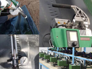
Electronic tensile machine
The electronic tensile machine has the characteristics of a compact structure and easy use. It can be used for tensile, compression, bending, shearing, peeling, tearing and other force tests with a maximum load of 100kN.

Geotextile tensile fixture
Test the elongation characteristics of geotextile and other textile fabric samples.

Geotextile pneumatic bursting fixture
Used for bursting and puncture tests of geotextiles.

Extensometer
The extensometer can perform repeated axial tensile tests and is mainly used to test the deformation of various materials, including metal materials, plastic materials, composite materials, etc.

Reagents
Distilled water and non-ionic wetting agent (general polyoxyethylene glycol alkyl ether with a volume ratio of 0.05%) are only used for soaking samples.
Test sample preparation
Number of test samples
Cut at least 5 specimens in the longitudinal direction (MD) and transverse direction (CMD).
Size of test samples
① Non-woven geotextiles, knitted geotextiles, geonets, geonet mats, clay geomembranes, drainage composite materials, and other products
The final width of each specimen is (200±1) mm, the specimen length meets the clamp spacing of 100 mm, and its length direction is parallel to the direction of the applied load.
② Woven geotextiles
For woven geotextiles, cut each specimen to about 220 mm wide, and then remove approximately equal numbers of side yarns from both sides of the specimen to obtain a nominal specimen width of (200±1) mm.
③Unidirectional, bidirectional and four-directional geogrids
For unidirectional, bidirectional and four-directional geogrids, the width of each specimen shall not be less than 200mm and shall be long enough to meet the clamp spacing of not less than 100mm.
Cut all ribs 10mm away from any node. (For unidirectional geogrid products with node spacing ≤10mm, the width of the prepared specimen should be 2 ribs wider than the required specimen width. When the specimen is clamped into the jaws, cut off the excess at both ends.)
The calculation of the test result (strength) should be related to the number of complete tensile ribs per unit width.
The specimen should contain at least one row of nodes or cross tissues in addition to the nodes or cross tissues held by the clamp (as shown below).
When the transverse pitch of the product is less than 75mm (transverse pitch: the distance between the starting point of one rib (force-bearing unit) and the starting point of the next rib), there should be at least 4 complete tensile units (tensile ribs) in its width direction.
When the transverse pitch is 75mm≤<120mm, at least 2 complete tensile units should be included.
When the transverse pitch is greater than 120mm, 1 complete tensile unit can meet the test requirements.

The marking points for measuring elongation should be marked on the midpoint of the tensile ribs in the middle row of the specimen. The two marking points should be at least 60mm apart and should be separated by at least 1 node or cross tissue.
If necessary, the marking points can be separated by multiple rows of nodes or cross tissues to obtain a minimum spacing of 60mm.
In this case, mark the points at the midpoints or nodes of the ribs, and the gauge length should be an integer multiple of the grid spacing.
Measure the nominal gauge length to an accuracy of ±1mm.
For three-dimensional geogrid, each specimen shall be not less than 200mm wide and have sufficient length to meet the clamp spacing of not less than 100mm. Cut the specimen and measure the width of the specimen according to Figures 4 and 5.

The marking point for measuring elongation should be marked at the center of the specimen node and should be separated by at least 1 node or cross tissue.
If necessary, the marking point can be separated by multiple rows of nodes or cross tissue to obtain a minimum spacing of 60mm.
In this case, the marking point should be kept at the midpoint of the rib, and the spacing length should be an integer multiple of the grid spacing.
Measure the nominal spacing length accurately to ±1mm.
⑤ Wet specimens for testing
When both the maximum wet load and the maximum dry load are required, the length of the specimen shall be at least twice the specified length, the specimen shall be numbered, and two specimens shall be cut from the middle, one for wet testing and one for dry testing. The specimen number shall be marked on each specimen.
For geosynthetics with severe wet shrinkage, the tensile strength shall be measured based on the maximum wet load and the initial width before soaking after moisture conditioning, with an accuracy of ±1mm.
Wet specimens
General
Wet specimens and tests are conducted under standard atmospheric conditions. The specimen is considered to be properly conditioned when the mass change of the specimen in successive weighings at intervals of at least 2 hours does not exceed 0.25% of the mass of the specimen.
Wet test conditions
The specimens used for wet tests shall be immersed in water at a temperature of (20±2)°C for at least 24 hours, which is sufficient to completely wet the specimen. To completely wet the specimen, a non-ionic wetting agent not exceeding 0.05% may be added to the water.
Test steps
1. Set up the testing machine
Before the test, adjust the clamp gauge to (100±3) mm (except for geosynthetics and geogrids using winch clamps), and select the load range of the testing machine so that the force value is accurate to 10N.
For geosynthetics with an elongation of εm>5%, set the tensile speed of the testing machine so that the elongation rate of the sample is (20±5)%/min of the gauge length; for geosynthetics with an elongation of εm≤5%, select a suitable tensile speed so that the average rupture time of all samples is (30±5)s.
The wet sample is tested within 3 minutes of removal.

2. Clamp the specimen
Clamp the specimen in the clamp in a centered manner. Note that the length direction of the specimen for longitudinal and transverse tests is parallel to the load direction.
The appropriate approach is to make the two pre-drawn marking lines across the width of the specimen and 100 mm apart coincide with the edges of the upper and lower clamps as much as possible.
3. Install the extensometer
Set marking points on the specimen at 60 mm intervals (30 mm from the center of the specimen respectively) and fix the extensometer.
4. Determine tensile properties
Start the test machine and apply a preload of 1% of the expected maximum load to determine the starting point of the initial elongation test. Continue to apply the load until the specimen breaks.
Stop the test and return the chuck to its initial position. Record and report the maximum load (accurate to 10N/m); record the elongation, accurate to one decimal place.
Based on the observed specimen conditions during the test, the unique variability of geosynthetics and relevant regulations, determine whether the test results should be rejected.
5. Determine elongation
Use a suitable recording device to measure the increment in the actual gauge length of the specimen at any specific load.

Calculation of test results
1. Tensile strength
Substitute the data obtained from the testing machine into formula (1) to calculate the tensile strength Tmax of each sample.
(1)Tmax = Fmax X c
Fmax — Maximum load recorded, in kN.
C — Calculated using the appropriate formula (2) or (3).
For woven geotextiles, nonwoven geotextiles, knitted geotextiles, geonets, geomatics, clay geomembranes, drainage composites and tri-grids and other products:
(2)C = 1 / B
B — Nominal width of the pattern, in meters.
(3)c = Nm / n
Nm — the number of tensile units within the 1m width of the sample.
n — the number of tensile units in the actual sample.
For composite products, select formula (2) or formula (3) according to the main load-bearing unit. For products with a double-peak curve (such as Figure 7), the results corresponding to the two peaks should be calculated separately.

2. Elongation under maximum load
Record the elongation under the maximum load of each sample, expressed as a percentage (such as AF in Figure 8), accurate to 0.1%. The elongation under maximum load can be calculated according to formula (4):
(4)e max = (△L – Lo’) / Lo x 100
e max — elongation at maximum load, %.
△L — elongation at maximum load, mm.
Lo’ — elongation when preload is reached, mm.
Lo — actual interval length, mm.

3. Elongation at nominal strength
Record the elongation at the nominal strength of each specimen, expressed as a percentage, accurate to 0.1%.
4. Cutting modulus
Determine the strength at a specific elongation, and calculate the cutting modulus at this specific elongation according to formula (5).
(5)J = F x c x 100 / e
J — Secant modulus, kN/m.
F — Strength measured at elongation e, kN.
C — Calculated according to the appropriate formula (2) or formula (3).
e — Specific elongation, %.
5. Average value and coefficient of variation
Calculate the average value and coefficient of variation of tensile strength, elongation under maximum load, and secant modulus of two groups of specimens in the longitudinal or transverse direction respectively.
Tensile strength and secant modulus are accurate to three significant figures, elongation is accurate to 1%, and coefficient of variation is accurate to 0.1%.
Summary
The above is the general content of the design of the geosynthetics wide strip tensile test method. There are still many details and implementations that are not listed in detail. If you are interested in this, please feel free to contact us for detailed data and content.